Let's start with putting together Marty's Legs…
Build x4
x4
x4
x4
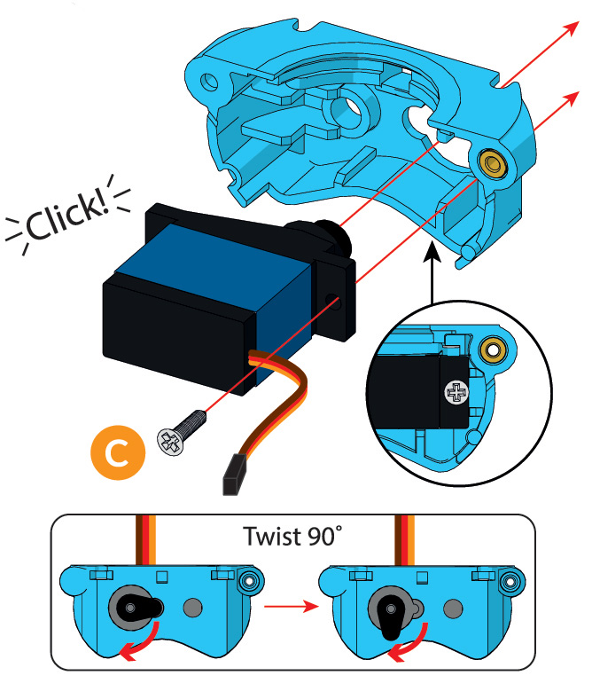
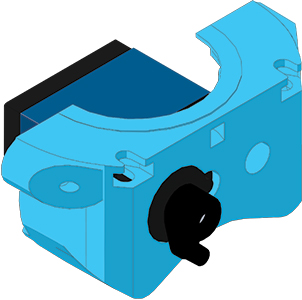
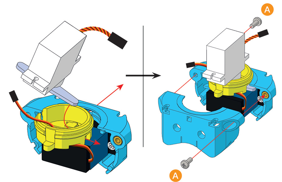
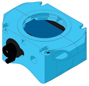
Take one of the blue Hip/Knee Servos and place it into the Servo Mount, securing it with a servo horn screw into the plastic - the video below shows this in detail.
Do this four times with all four blue metal servos. When you’re done, put two assemblies aside and go on to the next step.
Build x2
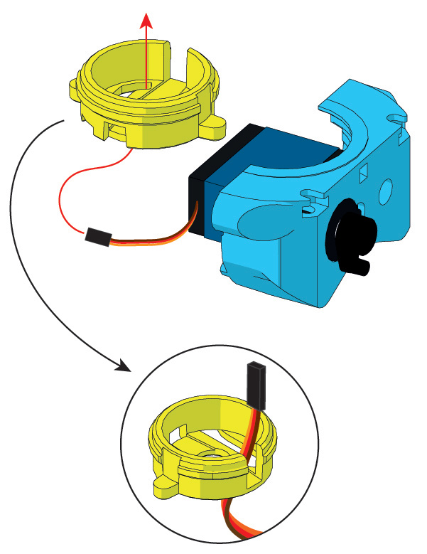
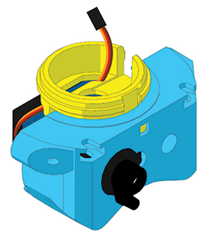
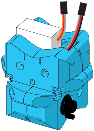
Pick up two Twist Shafts and two of assemblies you just made in Step 1. Poke the servo cable from the Hip/Knee Servo through the slot that looks like a letter ‘J’ in the Twist Shaft.
Then, insert the small lug on the Twist Shaft into the square hole on the Servo Mount as shown in the image, taking care not to pinch the cable!
Build x2
Grab one of the White Leg Twist Servos and gently turn the servo horn (The bit that looks like a propeller) so it is perpendicular to the Servo body - like shown in the Parts Guide. It only turns one way, so don’t force it.
Slide the servo into the Twist Shaft, and push both into the Servo Mount. The servo horn should be held within the servo mount.
Be careful with the orientation of the twist servo - the cable should be coming out out towards the servo horn of the metal servo from Step 1.
The cable from the blue servo should not be trapped under the horn of the Leg Twist Servo or be pinched against the twist shaft by the white servo, and instead should pass above it. In the next few steps make sure this cable does not get trapped by other sections of the leg - it should eventually find its way into Marty’s head.
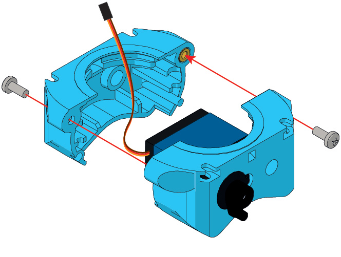
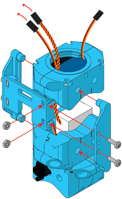
Lastly, close the assembly up with a Servo Holder, securing it with two M2.5x8mm bolts. Make sure the other lug on the twist shaft goes into the hole on the holder as it did for the Servo Mount in Step 2.
Build x2
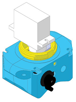
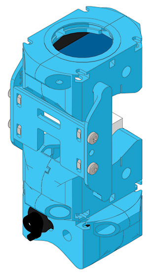
Using two Servo Holders, we’ll now finish off the knee. These parts clamp the Leg Twist Servo, and once screwed together should rotate freely on the Twist Shaft. There shouldn’t be a big gap between the upper and lower halves of the knee - if there is in yours, make sure you’ve locked the two Servo Holders on below the rib on the twist shaft.
Once again, make sure none of the cables get pinched between the plastics, and that they end up sticking out the top of the knee assembly.
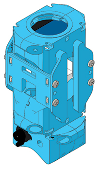
Please make sure that the Servo Holders are secured onto the lip of the Twist Shaft, as illustrated in the images below:
That’s the first part of your Robot done – the Knees! Now we’re going to move on to the hips and then finish the legs…
Build x2
Now using the remaining two assemblies you made way back in Step 1, stick a Servo Holder on the back with 2 x 2.5x8mm bolts for each one. That’s the hips done!
Build x8
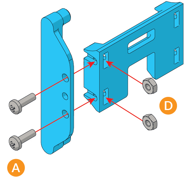
Connect a Leg Link to a Cross Brace using two M2.5x8mm bolts and two M2.5 nuts for each of the eight of these you need to build.
Make sure the Cross Braces are the right way up, otherwise your Marty won’t be able to walk properly!
Build x2
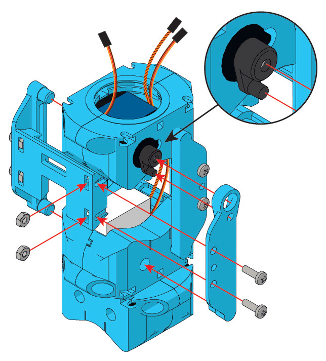
Now we’re going to start connecting all the bits of leg together. Using another Leg Link, two M2.5×8 Bolts and two M2.5 Nuts, attach the hips to the knees, slotting the pegs into the holes in the mounts.
Keep an eye on the orientation, particularly that the blue motor’s servo horn is poking out in the same direction as the wires from the servos
Build x2
Flip your leg around 180 degrees and attach a Cross Brace assembly from Step 6, and a Servo Leg Link in the same way as the previous step.
Make sure the Servo Leg Link engages with the two nubs of the Servo Motor in the knee, as shown in the pull-out circle.
Build x2
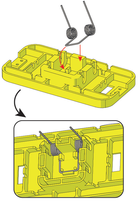
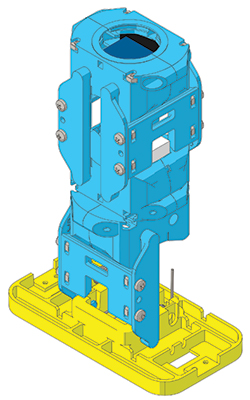
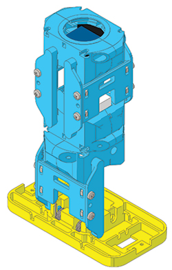
Take the two Foot Springs and clip them into the two feet. The springs are important as they help the knee motors to support Marty’s weight. When Marty leans to the side and lifts a leg up, Marty’s weight is split between the spring and the motor. That means a small motor can move a big robot!
Check that they’re proberly clipped under the two plastic tabs, and that the bracket runs between the guides as shown in the pull-out. This might be tricky to get in, but once in it’s not going to come out again easily!
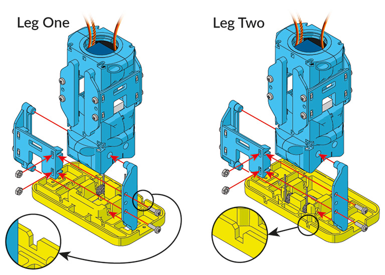
Now the last bit for the legs, we’re going to connect the feet to the legs. Make sure you follow the next step closely!
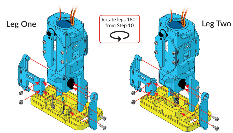
Step 10
Take your current leg and foot assemblies and screw them together with another Cross Brace assembly and Leg Link, again using 2 x 2.5x8mm Bolts and 2.5mm Nuts.
Important: again, this step must be completed twice, once for each leg. However, it is very important that the orientation of the foot is turned 180 degrees, as Marty’s left and right legs are different. Your Marty won’t be able to walk right if you forget this bit!
Step 11
Finally, take your leg assemblies and attach a final Cross Brace assembly and Servo Leg Link to each leg. Do this from the other side from Step 10, so the blue servo’s servo horn is now facing towards you rather than away from you. Again, make sure the Servo Link fits over the horn, same as Step 8.
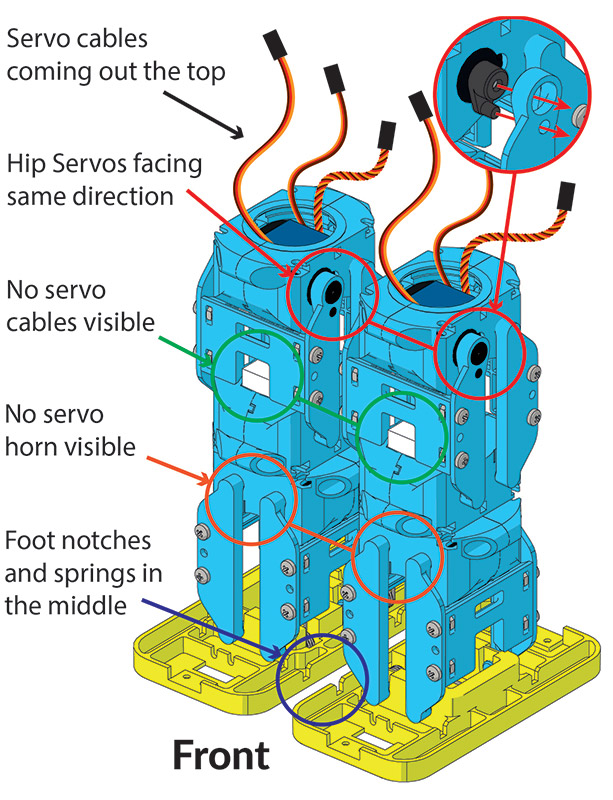
Just before moving on, check you’ve get everything in all the right places:
That’s your Marty’s legs done! Now let’s move on to the Arms…
