Step 15
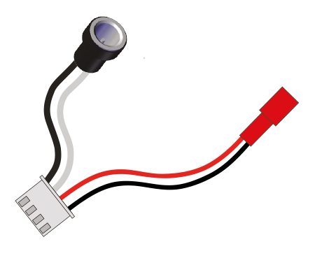
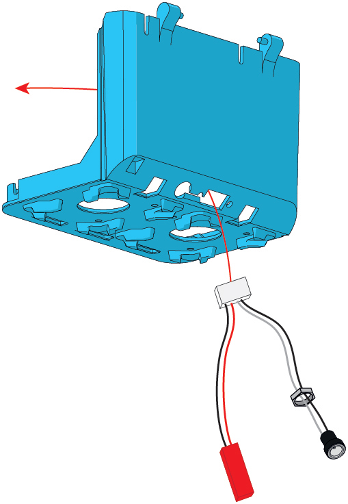
Take the Head Base and the Power Cable. Poke the wires and the retaining nut through the rectangular hole.
Step 16
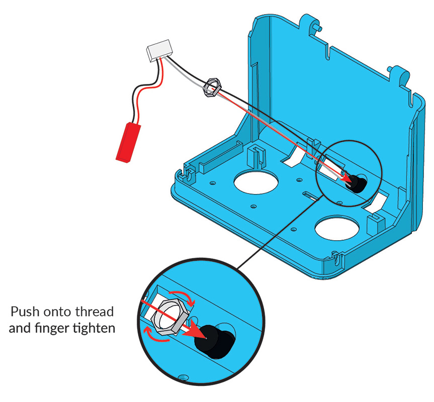
Press the socket gently into the circular hole. Tighten the retaining nut around the charging socket. Finger-tight will do just fine, this nut is just there to hold it in.
Step 17
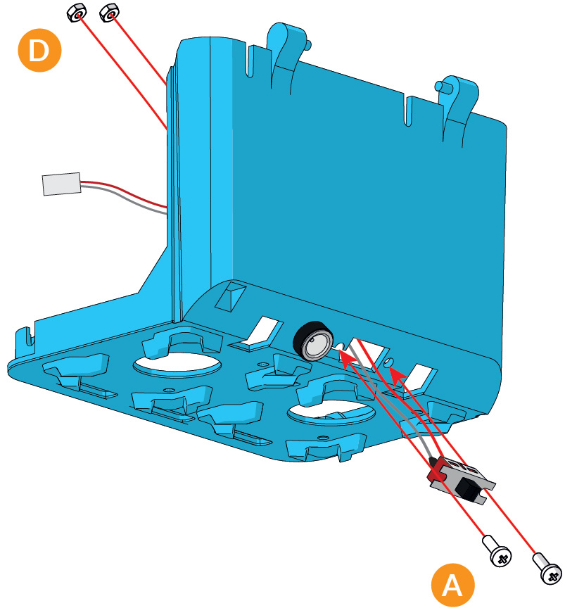
Take the On/Off Switch and pass the wires through the rectangular hole. Fasten the switch in place using two 2.5mm Nuts & Bolts. It should be possible to put the nuts on with your fingers - if you find it a bit too fiddly, try using tweezers to hold the nut in place.
Be careful with the switch, the metal cover can come unclipped if you force the switch into the slot. It should fit easilly.
Step 18
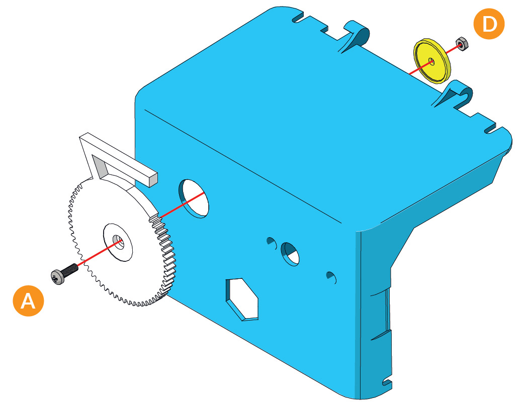
Insert a M2.5mm Bolt through the front of the Right Eye and secure it to the Head Face using the Eye Cup Washer and a M2.5mm Nut. The washer has one plain face and one hexagonal (nut shaped) face; the M2.5mm Nut should sit in the hexagonal detailed face.
Step 19 -Build x2
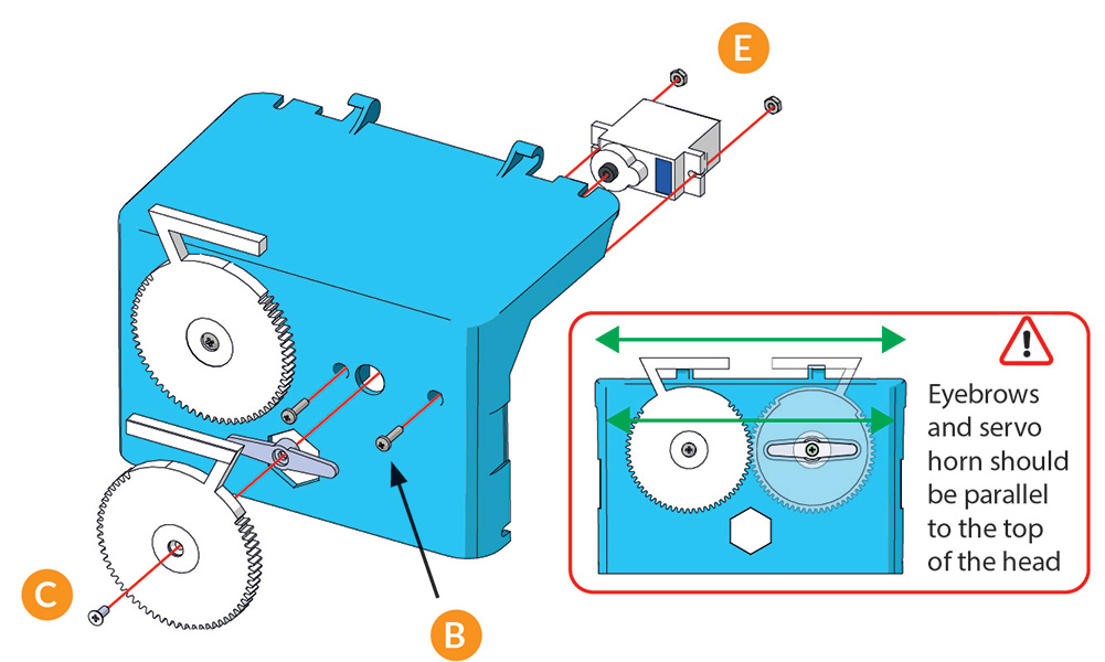
Note: This step uses thinner 2mm bolts and nuts to attach the servo to the head, the same as you used in Step 12 for the Arm servos. Also, the Left Eye is attached to the head through a Servo using a Servo Horn Screw – the one which has a pointy end.
First take two thin (M2x10mm) bolts and poke them through the holes to either side of Marty’s left eye hole. Grab an Arm/Eye Servo and screw it into place using the small nuts and the bolts you just inserted.
The initial angle of Marty’s eyebrows is important, this step should be followed carefully to give Marty the maximum range of expression (view video above or diagram below for more detail).
With the servo secured, take an Arm/Eye Servo Horn like the one in the picture and attach it to the face in the orientation shown in the pic. It’ll fit snugly on the servo spline. Take the Left Eye and put it over the servo horn, making sure the two eyes line up so both eyebrows are flat. Use a Servo Horn Screw (pointy) screw to secure the Left Eye to the servo.
And that’s the Head done! Now the best bit - putting it all together!

